Abstract: Various electrical parameters and switching signals of AM4 series microcomputer protection and ACR series multi-function power meters, collection and distribution room 10KV high-voltage cabinets and 0.4KV low-voltage distribution circuit are used. The system adopts the on-site local networking method. After networking, it communicates via the field bus and transmits the data to the background. The Acrel-2000 power monitoring system realizes the real-time monitoring and management of the power distribution circuit of the distribution board.
Keywords: Chang'an University; University Electricity Monitoring; Distribution Room; AM4 Series Microcomputer Protection; Acrel-2000; Power Monitoring System;
0 Overview
Chang’an University is located in Xi’an, the ancient capital of China. It is a national key university directly under the Ministry of Education of the People’s Republic of China. It is jointly established by the Ministry of Education and the Ministry of Transport, the Ministry of Land and Resources, the Ministry of Housing and Urban-Rural Development, and the Shaanxi Provincial People’s Government’s “four ministries and one provinceâ€. It is the country's first batch of "211 Project", "985 project superior discipline innovation platform", "111 plan", national construction of high-level university public postgraduate project" and "excellent engineer education training plan" key construction universities.
The project undertakes the power monitoring system of the school's headquarters Simon's distribution room. The monitoring host is located in the monitoring room of the power distribution room next door.
1 demand analysis
In order to ensure the production management of electricity load statistics and analysis and real-time monitoring of hazards. The on-site 10KV high-voltage power distribution cabinets and 0.4KV low-voltage power distribution cabinets need to carry out real-time online monitoring of voltage, current, power, and various switch signals. Once the monitoring point is monitored for abnormal parameters, the alarm can be detected in time and the relevant personnel take necessary measures to avoid safety accidents. The automatic meter reading function saves manpower and material resources, and the current trend curve function can intuitively display the working status and time of each loop.
data collection
It automatically collects the analog data of all 10KV loop AM4 microcomputer protection and 0.4KV circuit ACR multi-function instruments, and automatically collects on-site switch status and fault status switch data.
Supports real-time acquisition, automatic cycle acquisition (timing acquisition), configurable period (1 minute to 24 hours).
Support multi-thread processing mechanism, improve data collection efficiency, and data acquisition for multiple devices at the same time.
The real-time display of data adopts the visual display mode of the main wiring diagram of the power distribution room, and the disconnection and fault status of each loop can be seen directly.
Data query and display
Requirements can be easily achieved at all levels of management personnel inquiries, query interface can adapt to the requirements of various levels of management personnel can support flexible combination of conditional query.
The data display function is divided into three layers for operation level, management level, and decision level according to the different permissions of different users.
authority management
Requirements for different users to give different roles, can be authorized to function submenu, specific file records, data records.
The system requires a reasonably complete user security control mechanism, which can effectively protect the information resources in the application environment and prevent the loss, theft and destruction of information.
error alarm
Fault judgment and alarm have automatic fault judgment and use sound and light alarm function. The types of alarms include switch faults, voltage and current overruns, and field computer protection and monitoring system communication faults. The alarm time is automatically entered into the system database to facilitate the user's query. The staff can always grasp the real-time running status of the Ximen distribution room of the Chang'an University Headquarters, find the failure of the power distribution and operation, and make corresponding treatment to improve the management efficiency of the transformation and distribution, and improve the power. System security and reliability.
2 system solutions
Acrel-2000 system Acrel-2000 system according to the actual situation of the Chang'an University Headquarters Simon distribution room, the overall network structure using shielded twisted pair 7 bus directly to the monitor room console serial port server to protect the power distribution station Power monitoring system transmission stability and real-time performance. As shown below:
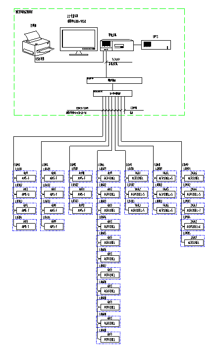
System structure
On-site Simon Power Distribution Room Total 10 AM4-I comprehensive protection, 1 AM4-U comprehensive protection, low voltage part total 2 ACR330ELH multi-function meters, 2 ACR220EL multi-function meters, 41 ACR120EL multi-function meters, total divided into 7 The RS485 bus is connected to the serial port server in the desk of the duty room.
1) Station control management
Station management The management personnel of the power monitoring system are the direct windows of human-computer interaction. In the west gate distribution room project of Chang'an University, it mainly refers to the monitoring host placed in the monitoring room.
2) Network communication layer
The communication layer is mainly composed of a bus network. The main function of the bus network is to realize on-site microcomputer protection and data exchange between the low-voltage multi-function instrument and the station control and management layer, so that the distribution system management is centralized, informatized, and intelligent, which greatly improves the security of the distribution system. , reliability and stability have truly reached an unattended purpose.
3) Field device layer
The field device layer is a data acquisition terminal, which is mainly composed of a microcomputer protection device on a 10KV power distribution cabinet and a multi-function power meter with a 0.4KV low-voltage power distribution circuit. The smart device is connected through a shielded twisted pair RS485 interface and is connected via a MODBUS protocol bus. The monitoring host performs networking and implements remote control.
Microcomputer protection device and low-voltage power meter on-site connection
On-site microcomputer protection devices and low-voltage multi-function power meters are connected in a hand-in-hand manner through shielded twisted pair (RVSP2*1.0). Each bus connects about 5 microcomputers and about 25 low-voltage power meters. The specific connection diagram is as follows:
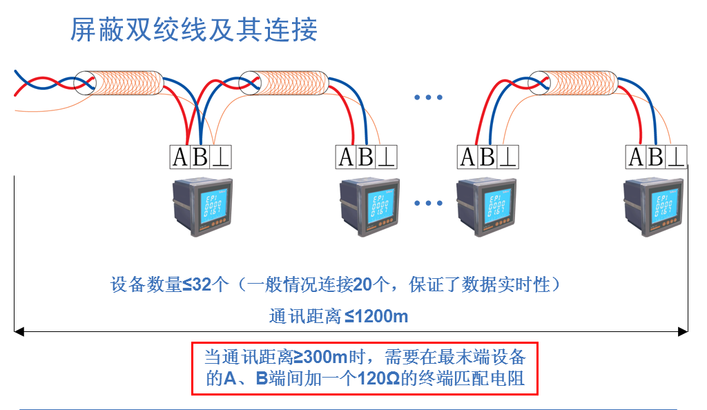
Communication line connection diagram
3 system function
The real-time monitoring system diagram of the power distribution system is the main monitoring screen, and it mainly monitors the running status of all circuits of the West Gate Distribution Room of Chang’an University in real time. In the system diagram, you can intuitively see the operating parameters and status of each 10KV distribution cabinet and low-voltage inlet and outlet loops, such as: three-phase voltage, current, active power, reactive power, power factor, frequency, and so on. As shown below:
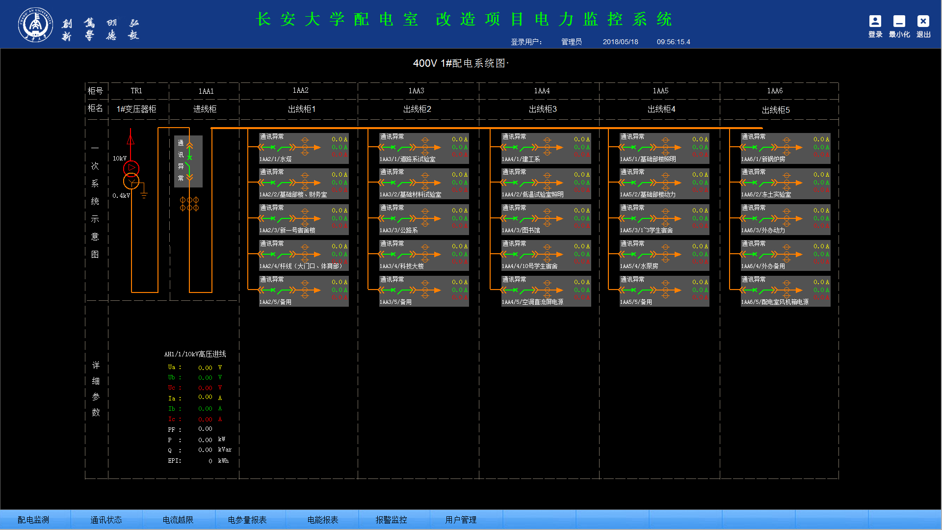
Distribution room system diagram
The event alarm recording function mainly completes the recording of the alarm information events occurring within the query time period and the occurrence time, providing a basis for the on-duty personnel and analyzing the cause of the accident.
The parameter reading function mainly inquires about the electrical parameters of 10KV distribution cabinets and low-voltage distribution circuits. Supports electrical parameter query at any time, with functions such as data export and report printing. The names of the loops in this report are associated with the database to facilitate the user to modify the loop name.
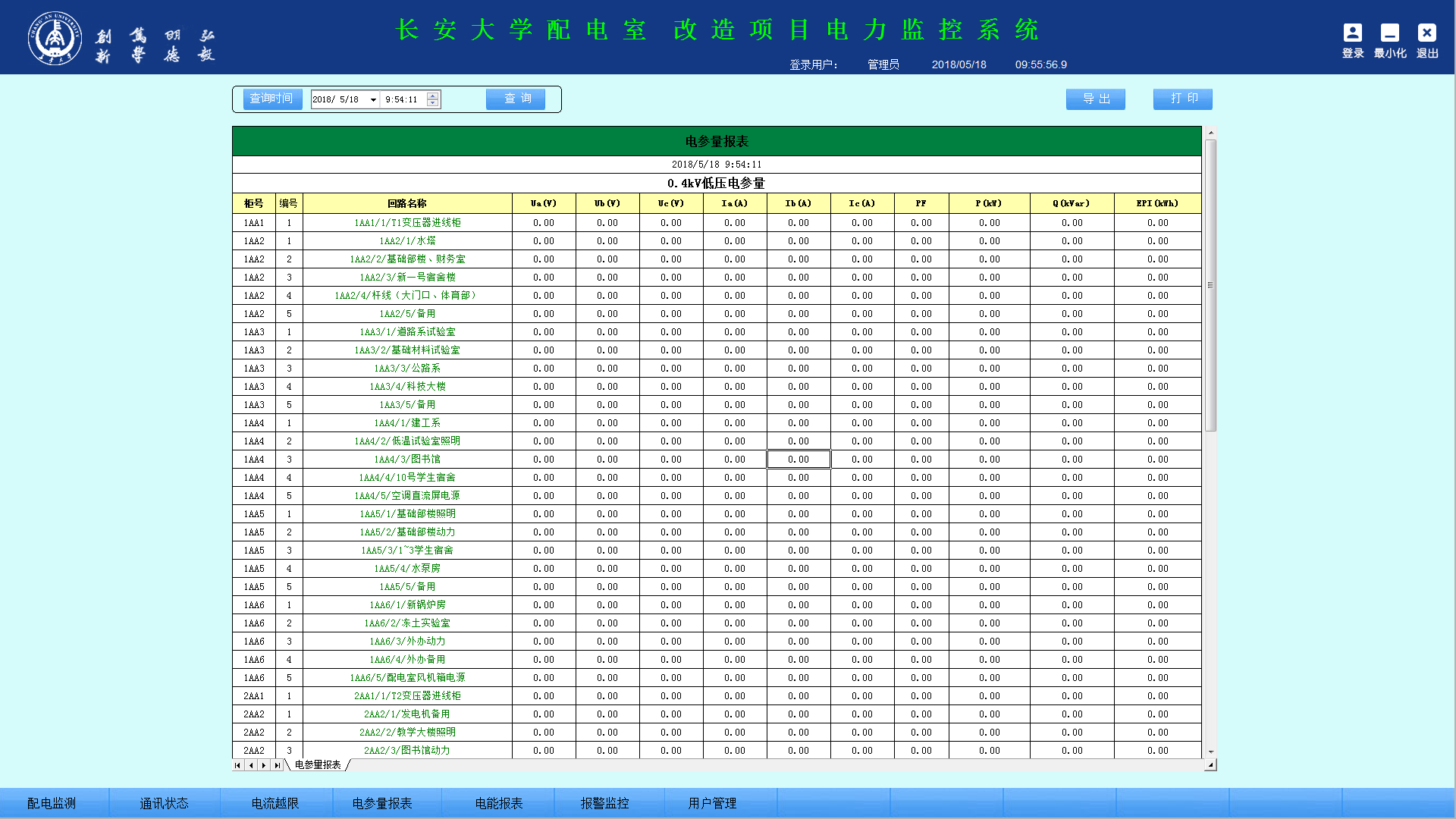
Electrical parameter report
The schematic diagram of the system communication structure mainly shows the networking structure of the system. The system adopts a hierarchical distributed structure and simultaneously monitors the communication status of the equipment at the bay level. Red indicates normal communication and green indicates abnormal communication.
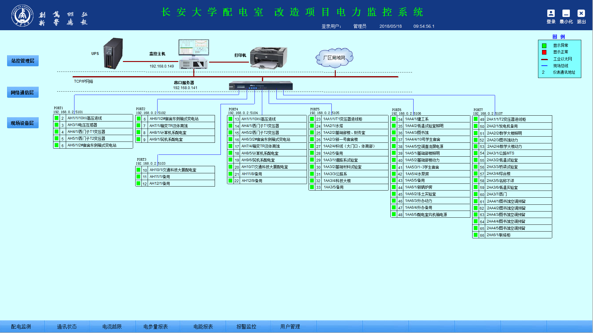
Communication structure diagram
4 Conclusion
In the application of power distribution facilities today, the distribution security of projects in colleges and universities is of utmost importance. The application of the Acrel-2000 power monitoring system described in this article in the west gate distribution room of Chang’an University can achieve power distribution for power distribution stations. Real-time monitoring of loop power. The system analyzes and processes the collected data. It displays the running status of each 10KV distribution cabinet loop and 0.4KV low-voltage distribution inlet and outlet loops in the central power distribution room in real-time. The pop-up alarm dialog box and alarm can be displayed for the closing and closing of the load. The voice prompts that the system is safe, reliable, and stable, ensuring the reliability of electricity use in college buildings.
Square Bottle,Spray Pump Cosmetic Bottle,Hand Sanitizer Alcohol Spray Bottle,Pet Plastic Spray Bottle
Guangzhou Moomi Packaging Co.,Ltd , https://www.m-mip.com