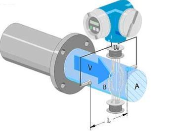
 In the operation of the electromagnetic flowmeter, the fault can be divided into two categories: The first type is the fault of the instrument itself, that is, the fault caused by damage to the instrument structure or the component; the second type is the fault caused by external reasons, such as improper installation flow Distortion, deposition and scaling. This chapter focuses on the application and the above-mentioned second type of external causes of failure. Classification according to the time of failure, can be divided into: 1 debugging failure; 2 failure during operation. Debugging faults appear in the initial stage of debugging after new equipment installation. The main reason is that the instrument is selected or improperly set up, and the installation is not proper. Run-time faults occur after a certain period of operation, mainly due to impurities in the fluid adhering to the electrode lining, and new interference sources such as changes in environmental conditions. According to the external sources of failure analysis from three aspects: 1 caused by the piping system and installation; 2 caused by the environment; 3 caused by the fluid. Source 1 is mainly demonstrated during the commissioning period; Sources 2 and 3 are both present during commissioning and operation.
 A debugging <br> <br> Fault This fault can occur when the electromagnetic flowmeter installed with initial debugging, but an improved troubleshooting, generally will not appear again later under the same conditions. The common debugging faults include three reasons: improper installation, environmental interference, and fluid characteristics.
1. The piping system and installation are usually faults caused by incorrect installation position of the electromagnetic flow sensor. Commonly, for example, the flow sensor is installed at the high point of the pipe network where accumulation of entrapped gas is easy; there is no back pressure after the flow sensor, and the liquid is directly discharged. The human atmosphere forms a non-full pipe in its measuring pipe, and it may be empty on a vertical pipe running from top to bottom.
2, the environment is mainly the pipe stray current interference, space electromagnetic interference, large motor magnetic field interference. Stray current disturbances in pipelines are usually measured by good individual grounding to obtain satisfactory measurements, but if there is strong stray current in the pipeline (such as the electrolytic shop pipe), it may not be overcome, and measures must be taken to exclude flow sensors and piping (see below). Case 12). Space electromagnetic interference - generally through the signal cable I, usually single or multi-layer shielding to protect, but also encountered shielding protection can not be overcome (see Case 10).
3, Fluids Fluids containing uniformly distributed fine air bubbles usually do not affect the normal measurement, but the measured volumetric flow is the sum of both liquid and gas; the increase in air bubbles will cause the output signal to fluctuate if the air bubbles are large enough to flow over the electrode to cover the entire electrode surface , Make the electrode signal circuit break instantaneously, the output signal will produce greater fluctuation. Low-frequency (50/16 Hz-50/6 Hz) rectangular-wave excitation magnetic flowmeters produce slurry noise when the liquid contains more than a certain amount of solids, and the output signal will also fluctuate to some extent. When two or more liquids are used as a pipe mixing process, if the conductivity of the two liquids (or their respective potentials with respect to the electrodes) is different, the flow sensor will enter the flow measurement before the mixing is not uniform, and the output signal will also fluctuate. The poor matching of the electrode material and the measured medium produces chemical effects such as passivation or oxidation. The formation of an insulating film on the surface of the electrode, as well as electrochemical and polarization phenomena, will interfere with the normal measurement.
After two failures, failures <br> <br> run through early commissioning and running some time during the operation of emerging common causes are: flow sensor attached to the inner wall layer, lightning strike, changes in environmental conditions.
1. Internal Wall Adhesion Layers Electromagnetic flowmeters have a much higher chance of measuring suspended solids or contaminants than other flowmeters. The probability of faults occurring in the inner wall adhesion layer is relatively high. If the adhesion layer conductivity is similar to the liquid conductivity, the meter can still output signals normally, but only change the flow area, forming a hidden failure of the measurement error; if the high conductivity adhesion layer, the electromotive force between the electrodes will be short circuit; if the insulating adhesion layer The electrode surface is insulated and the measurement circuit is disconnected. The latter two phenomena will make the instrument unable to work.
2, lightning thunder and lightning shock induction transient high voltage and inrush current in the line, enter the instrument will damage the instrument. There are three ways to introduce a lightning damage meter: the power line, the sensor flow signal line and the excitation line between the converter. However, analysis of damaged components from lightning failures causes most of the induced high voltage and surge currents of the fault to be introduced from the control room power lines, and the other two approaches are less. It also learned from the scene of a lightning accident that not only did the electromagnetic flowmeter malfunction, but the other meters in the control room often experienced lightning strikes at the same time. Therefore, the use of the unit to understand the importance of setting up the control room instrument power line lightning protection facilities.
3, the main cause of changes in environmental conditions in the same period as the fault environment during the debugging period, but the interference source is not in the debugging period and then involved in the operation period. For example, an electromagnetic flowmeter with unsatisfactory grounding protection has normal operation due to no interference source during the commissioning period. However, new interference sources (for example, pipelines near the measuring point or where welding is performed farther away) interfere with the normal operation of the instrument. , There is a large fluctuation in the output signal.
Other Checking Fixtures Components
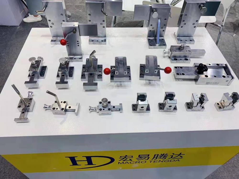
Checking Fixture A piece of equipment used to hold a part in a fixed position for CMM Checks or other. It is sometimes referred to as CMM Fixture. Checking Gauge A piece of equipment used as an inspection tool which would help make decisions regarding the quality status of a product. The inspection fixture is composed of many accessories. Such as Slider, mechanism, location block, tooling ball assembly, spring wire, bushing and Checking Pin, go no-go gauge, and so on. We entered into automotive checking industry from 2012 year. And passed ISO9001

Other Checking Fixtures Components,checking components,custom pin,captive pin
Kunshan Hongyi Tengda Mold Hardware Co.,Ltd , https://www.hdchecking.com